
Assembly & Measurement of a 3dB Splitter
Lately, I needed a 3dB splitter for an HF (1…30MHz) measurement project. Instead of buying myself a splitter, I decided to build it on my own. After measuring the performance I am satisfied with the result.
Introduction
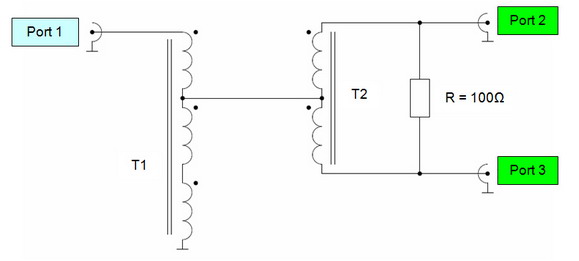
The circuit of this splitter is nothing new. It is known as a 0º & 180º Hybrid. The big advantage of this hybrid is that it can be used to force the equal current in two different loads. This means that the incoming signal will always be split equally, independent of the termination of its ports.
On the other hand, these hybrids can also be used to combine two signals without affecting the input impedance of the other port. In this case, they are called “combiner”.
The three most popular HAM Radio applications are:
- Distribution of an HF signal on two receivers (splitter)
- Measuring intercept point of 3rd order (combiner)
- Combining signals of receiving antennas, i.e. phased beverages (combiner)
Preparation
For the ferrite core, I choose Amidon 61 material which is generally a good choice for broadband transformers between 1 – 30MHz due to its low losses. The permeability of the 63 material is specified with µ=125.
The following data has been taken out of Amidon’s datasheet:
<td width="115">
  <p align="center">
    <strong>Permeability</strong>
  </p>
</td>

<td width="115">
  <p align="center">
    <strong>Resonance</strong>
  </p>
</td>

<td width="115">
  <p align="center">
    <strong>Wide Band</strong>
  </p>
</td>

<td width="115">
  <p align="center">
    <strong>AL</strong>
  </p>
</td>
<td width="115">
  <p align="center">
    <strong>125</strong>
  </p>
</td>

<td width="115">
  <p align="center">
    0.2 – 10MHz
  </p>
</td>

<td width="115">
  <p align="center">
    <strong>10-200MHz</strong>
  </p>
</td>

<td width="115" align="center">
  75
</td>
The following ferrite cores could be used:
<td width="148" valign="top">
  <strong>Outer Diameter</strong>
</td>

<td width="133" valign="top">
  <strong>Inner Diameter</strong>
</td>
<td width="148" valign="top">
  12.7mm
</td>

<td width="133" valign="top">
  7.14mm
</td>
<td width="148" valign="top">
  21.0mm
</td>

<td width="133" valign="top">
  13.1mm
</td>
<td width="148" valign="top">
  29.0mm
</td>

<td width="133" valign="top">
  19.05mm
</td>
Since I had already a small case with 3 BNC plugs available I choose FT-82-61.
Two ferrite cores are necessary:
- A trifilar wounded core (7-10 rounds)
- A bifilar wounded core (7-10 rounds)
For 10 rounds on an FT-82-61 19cm of wire are needed. Including a few spare centimeters, I prepared 5 x 25cm of magnet wire (don’t use blank wire) with a 1mm diameter.
Since we are dealing with HF, a metal film resistor (100Ω) should be used across Port 2 and Port 3. Metal film resistors have better HF performances than standard carbon film resistors.
Assembly
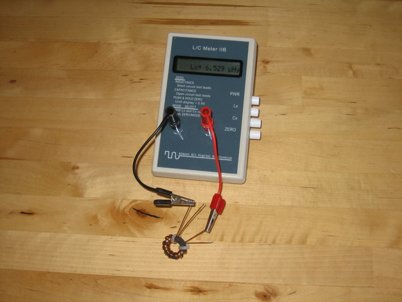
The wound cores should more or less look like in the picture below. The inductance was calculated on the paper with a value of 6,9 µH. The measured value was 6,53µH and therefore considered as ok.
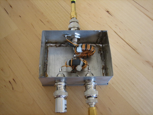
The two ferrite cores were mounted in a tinplate housing with three BNC plugs. The solder joint between the windings of T1 was covered with a heat shrink tube to avoid ground closures. The 100Ω metal film resistor was soldered across the plugs of port 2 and port 3. The picture below shows the assembled splitter with already connected coaxial cables.
Measurement setup
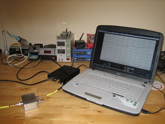
The following measurements were made with a Vector Network Analyser (TAPR VNA) and should give a good impression about the performance of the hybrid. Please note that my “poor mans VNA” only is capable of measuring S11 and S21 at the same time.
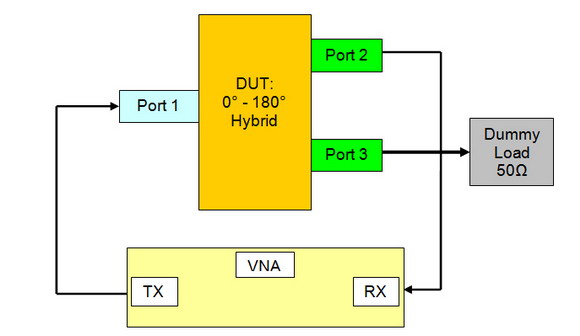
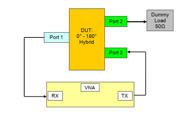
A fixture calibration was made to exclude the cables and connectors of the measurements. The picture below shows the setup.
Measuring Signal Distribution port 2
In this measurement, the signal distribution between Port 1 and Port 2 was be analyzed. Please note that Port 3 was terminated with 50 Ohm.
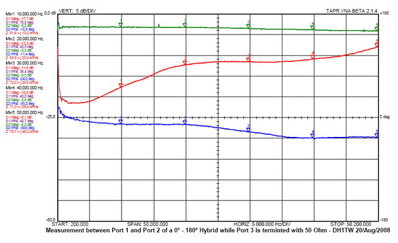
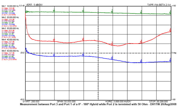
It can be seen that the attenuation (S21 green) is almost continuously 3db. At 50 MHz it drops down to 4,2dB. The impedance matching (S11 red) is acceptable up to almost 50MHz. The phase (S21 blue) is constant up to 25MHz with about 10° and ending up at 34° at 50MHz.
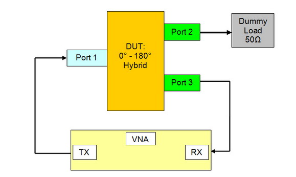
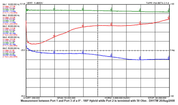
Measuring Signal Distribution port 3
In this measurement, the signal distribution and the impedance matching of port1 were analyzed.
Comparing the plot and the values of the markers with the ones from ‘Measuring Signal Distribution port 2 it can be seen that both ports behave symmetrically. Since also the phase is symmetrical, the relative phase difference between port 2 and port 3 is 0º.
Measuring Impedance Matching of port 3
In this measurement, the impedance matching of port 3 was analyzed.
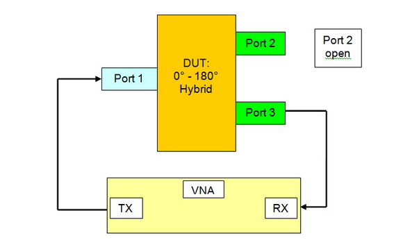
Measuring Signal Distribution with mismatch
In this measurement, the signal distribution was analyzed with a mismatch on port 2 (open).
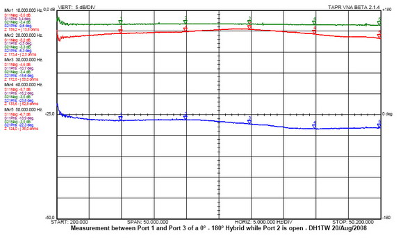
It can be seen that the attenuation (S21 green) stays constantly at 3db. This proofs that the signal is equally shared between port 2 and port 3, independent of their impedance. Note that the mismatch is transformed into the impedance of port 1 (S11 red). The phase (S21 blue) isn’t affected.
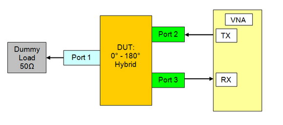
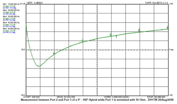
Measuring Port Isolation
With this setup, the isolation between port 2 and port 3 was measured to see the dependencies between these two ports.
Conclusion
In this article, a 0º & 180º hybrid, known as ‘splitter’ or ‘combiner’ was build and analyzed. The performed measurements show a very good performance in the desired frequency range between 1-30MHz. The hybrid could be used on frequencies up to 50MHz with some minor degradation in performance.
