
A simple broadband 4:1 Balun Transformer
During the summer break, it became quiet here on my blog. While Instead of chilling at the beach, I spend a lot of time on new Hardware and Software projects. Most of them are done, and now it’s time to document them. In this blog post, I want to share the construction of a versatile 4:1 Balun. In combination with a ladder line and an automatic Antenna tuner, you can use any dipole on almost all frequencies.
Why do you need a Balun?
Depending on the length of your dipole, the impedances at the feed point can get quite high. Built-in Automatic Tuners usually cover only impedances between 20-200Ohm. With the 4:1 Balun, we transform the high impedances down into the range of the automatic tuner.
Design
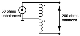
I decided to go with the old Ruthroff Design which can be seen in the picture below. It’s a transmission transformer and does not provide galvanic isolation. My BalUn (Balanced-Unbalanced Transformer) is broadband and can be used from 1..30MHz.
10 bifilar turns are mount on an Amidon FT-240-61 ferrite core. I used 1,5mm PTFE (Teflon) insulated wire. With high impedance, high voltages can appear on the wires, so it’s better to have proper insulation!
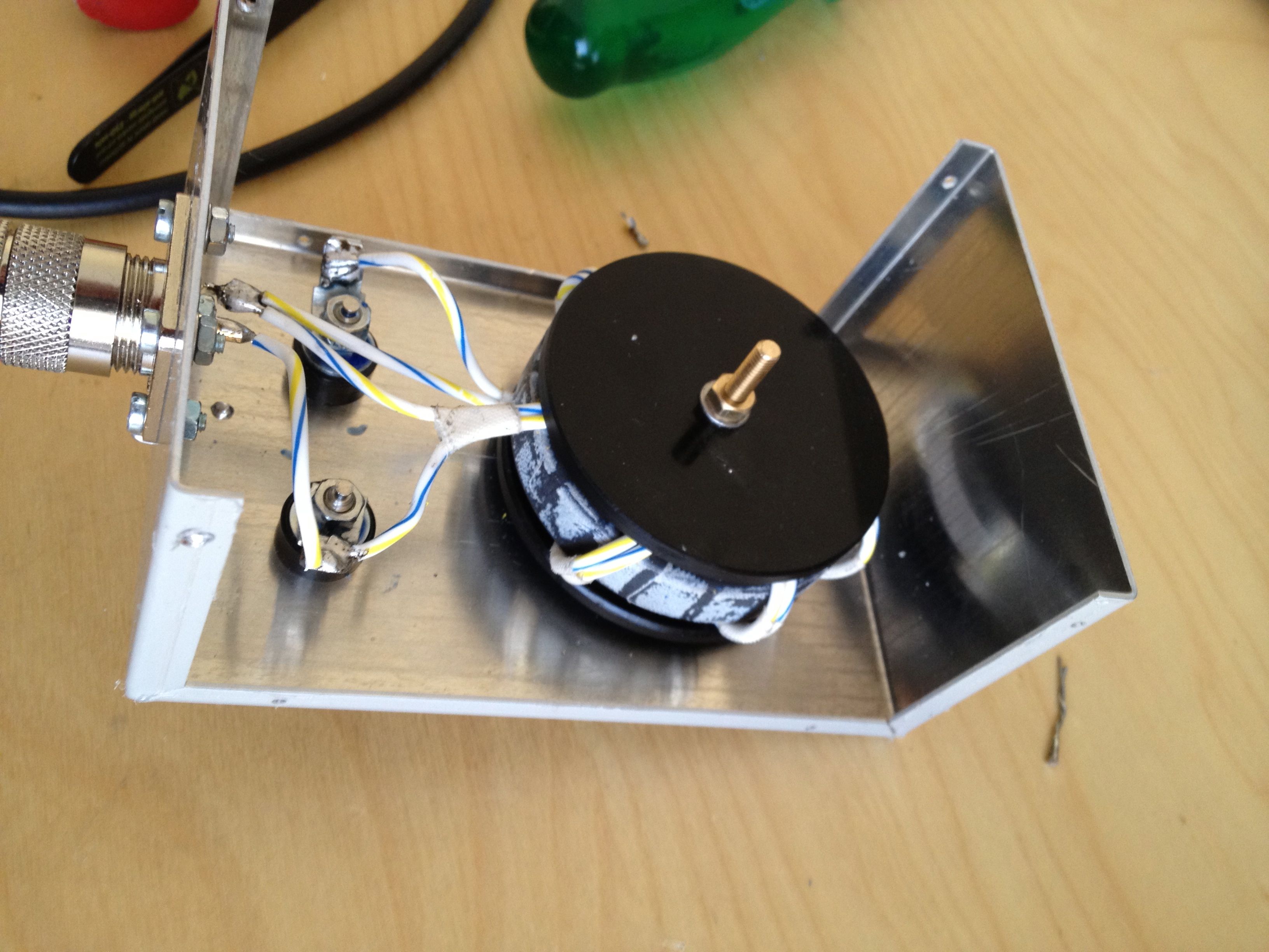
The Balun is mounted in a sheet metal housing which I bought at the local electronic store. The parallel wire (450 Ohm ladder line is connected through two Banana jacks.
Assembly
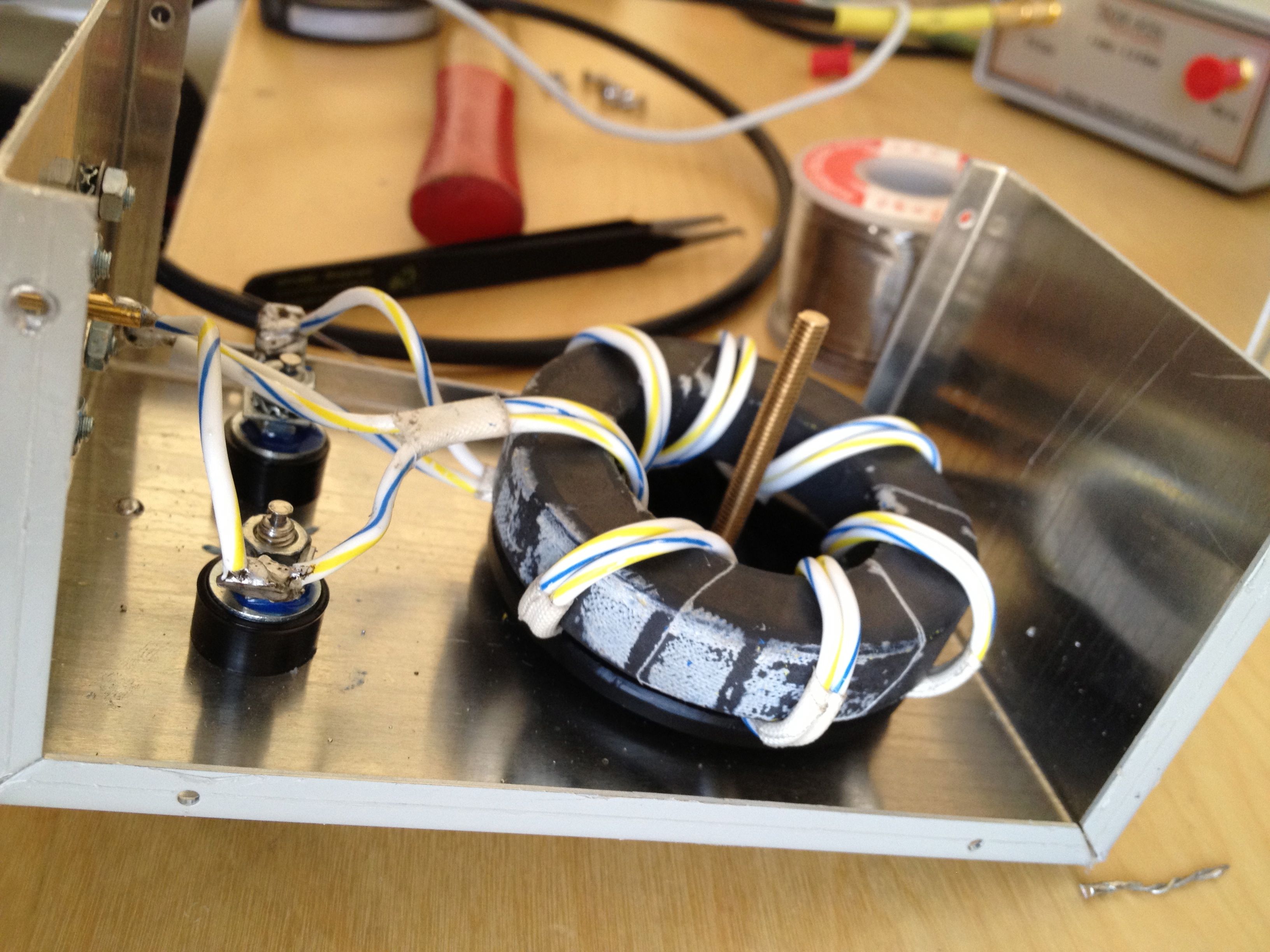
The picture above and below show the bifilar turns on the FT-240-61 ferrite core. Note: This was the prototype that only had 7 turns!
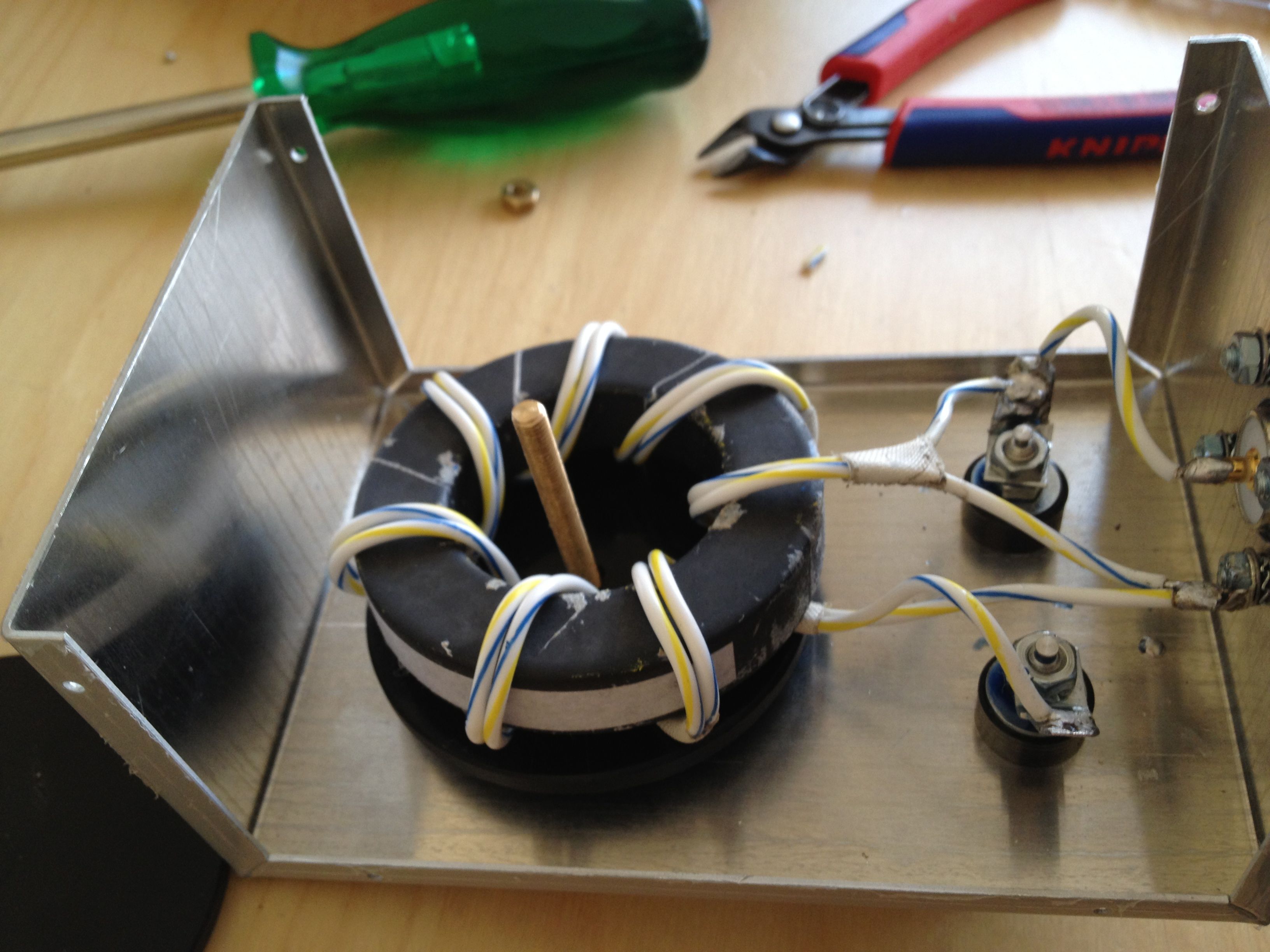
To fix the core properly, I used on both sides of the balun a Delrin (POM - Polyoxymethylene) washer, which was mounted with a long M4 screw on the chassis.
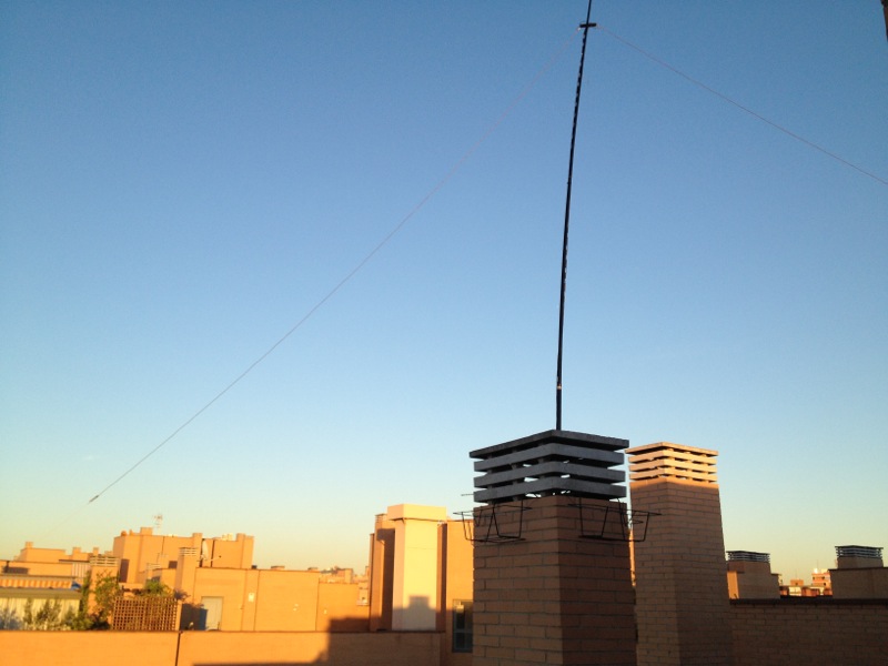
The Balun in action is shown below
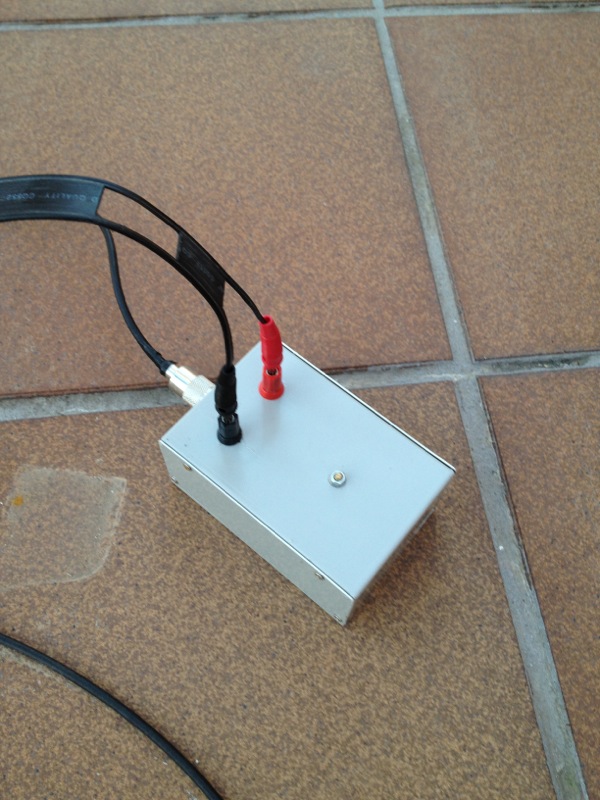
with my 2x5m long Inverted-V Dipol
Some Considerations
As mentioned in the footnote of the pictures I built two versions of the 4:1 BalUn. The first one with 7 bifilar turns and the second one with 10 bifilar turns. As it turned out, the 7 turn version was only usable from 7-30MHz. But since I wanted to create a universal, broadband BalUn covering 1.8MHz - 30MHz I had to add another three turns.
When winding the turns on the ferrite core, make sure the wires are always in parallel. Avoid any gap between the wires, since this results in an undesired impedance variation. I always fixate the two wires every 2-3cm with a small strip of adhesive tape.
Performance
I measured the Performance with my DG8SAQ Vector Network Analyzer (VNWA). Since the BalUn has a ratio of 4:1 I had to terminate the antenna-end with a 200Ohm resistor. The plot below shows the S11 / VSWR curve from 1..30MHz which does not exceed 1:1,36.
I’m satisfied with the result.
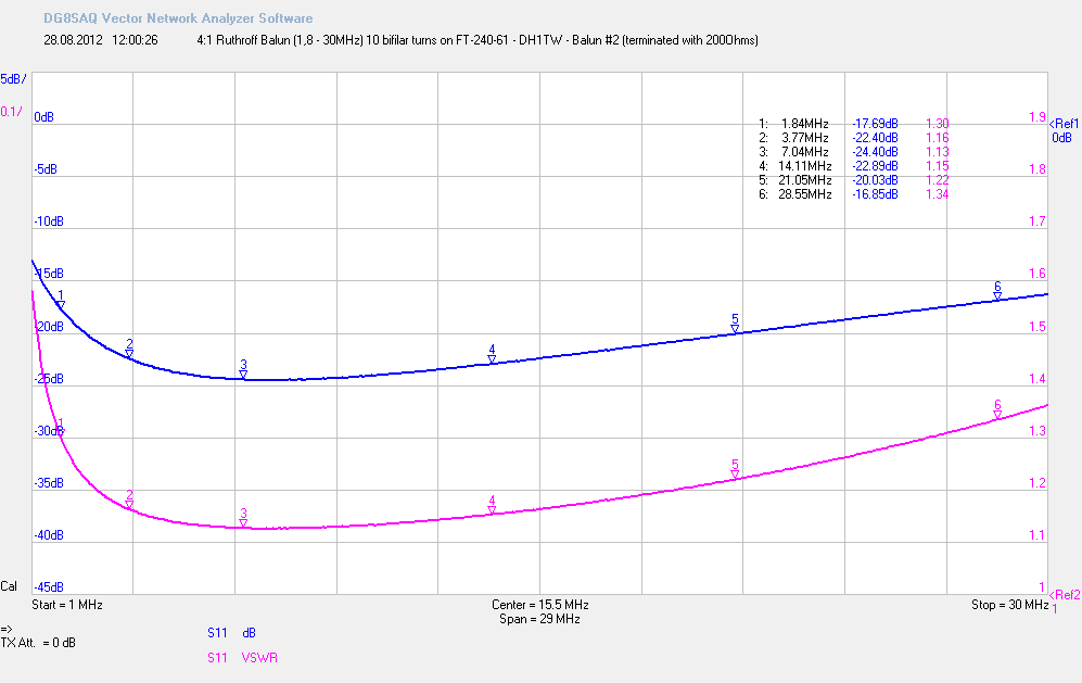
S11 / VSWR of the 4:1 Broadband BalUn
Resources
- Ferrite Cores, PTFE insulated wire and Delrin washers can be bought from DK3YD / Bausch-Gall GmbH.
- DK3YD also sells professionally manufactured 4:1 BalUns BR-41-100-A (low power) and BR-41-750-A (high power)
- Martin Ehrenfried, G8JNJ published a nice article about the construction of Ruthroff Transformers
