
Bandscope Modification Yaesu FT1000MP
In 2007 several SDR (Software Defined Radio) kits became available for Ham Radio purposes. Since most of these kits are just single band receivers, another easy solution was needed to benefit from the PC-based Signal Processing on multiple bands. With the Yaesu FT1000MP, a full coverage short wave receiver was already available in the shack. Why not reuse the already available hardware instead of spending money for a couple of additional monoband SDRs?
After studying the schematics of Yaesu’s FT1000MP it was decided to tap the IF (Intermediate Frequency) with an already available SDR-Kit. This article documents the performed analysis and conducted work necessary to perform this modification.
Prerequisites
Please note that advanced soldering skills are necessary to perform this modification. SMD soldering equipment is recommended. If this “surgery” isn’t conducted with the necessary precaution, it’s an easy way to damage the transceiver seriously.
Please note that the author isn’t liable for any damage caused as the result of attempting to carry out this modification! Although this modification was developed under best engineering practice, there still might be other or better alternatives available to tap an IF signal.
Analysis
The FT1000MP has two builds in receivers, which work more or less independently of each other. In each of these receivers, several filters can be found. Some of them are optional and can be selected from the front end, but there are a lot of internal filters in the IF which also has to be considered while searching for the perfect tap point.
Computer Soundboards are capable to handle an input spectrum up to 192kHz. Therefore the tapped signal should be as wide as possible.
The Main Receiver has three Intermediate Frequencies:
- IF on 70.455MHz
- IF on 8.125MHz
- IF on 455kHz
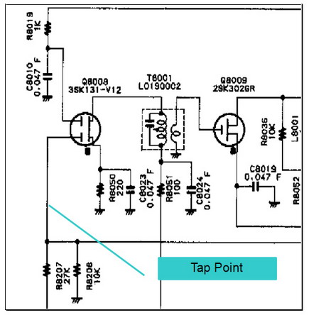
In the technical description of the first mixer circuit the following section can be found:

Unfortunately, the crystal filters XF1001/1002 narrow the bandwidth to 12kHz for this and all following stages.
The Sub Receiver has only two Intermediate Frequencies:
- IF on 47.21MHz
- IF on 455kHz
In the technical description of the first mixer circuit the following section can be found:
At least the Sub Receiver offers theoretically a signal with 40kHz bandwidth at the output of the first mixer circuit.
Obviously, due to the bigger bandwidth, the tap point will be in the circuits of the Sub Receiver.
Tap Point Selection
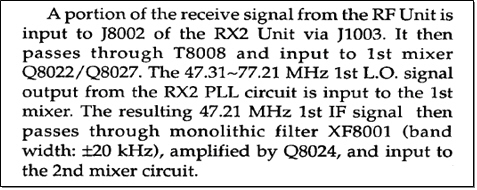
Below is a section of the Sub Receiver schematic with the first and the second mixer circuits.
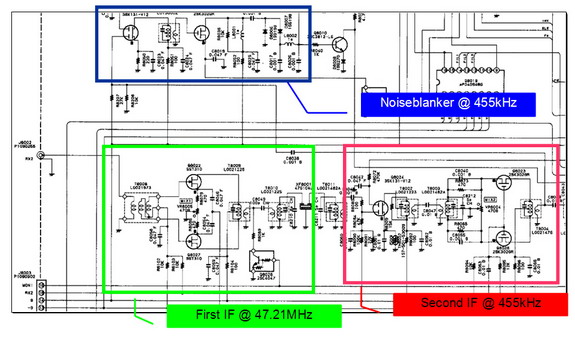
The following drawing shows a more detailed few of the second IF:
The wanted 455kHz signal can be found between the Mixer’s combiner (T8004) and the following splitter (T8005). The signal between T8004 and T8005 is directly connected to the Noise Blanker Circuit. Therefore a reasonable possibility is to tab the wanted signal at the Gate of the Noise Blanker Amp (Q8008).
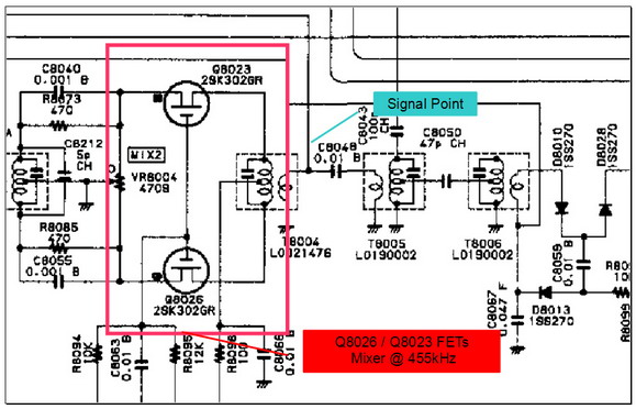
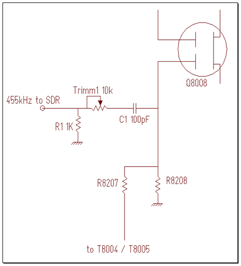
The following drawing shows the Noiseblanker’s amp.
The signal will be tapped with a 100pF, directly connected to the gate of Q8008. The level can be adjusted with a potential divider (Trimm1 / R1). The following drawing shows how to tap the signal.
Modification
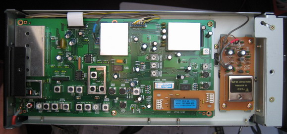
The tap point is located on the RX2-Unit board. This board is mounted on the right side of the transceiver.
Unscrew and open the chassis
Unscrew the RX2-Unit board and disconnect the cables
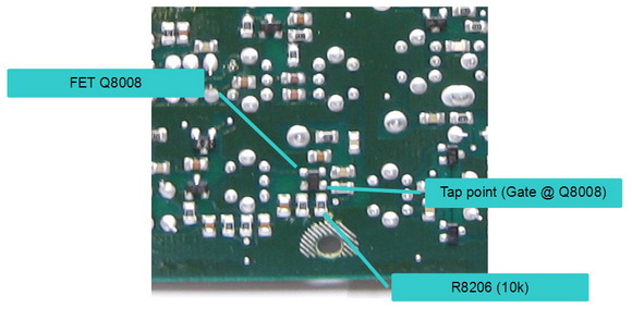
The bottom side should look like this:

The FET Q8008 is located close to the lower central mounting hole.
Connect the coupling capacitor C1 to the gate of Q8008
Connect Coax Cable to coupling capacitor C1
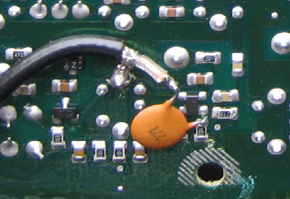
Isolate PCB from bare wire
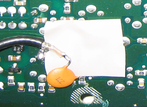
cover all bare wires with adhesive tape
Reattach the PCB and fasten the screws
Reconnect all cables
Route the coaxial cable outside (I.e. through the amplifiers ventilation slots)
Please note, that the resistor (R1) and trimmer (Trimm1) have been installed on the PCB of the SDR.
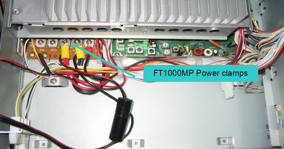
In case an FT1000MP DC without an internal power supply is used, an SDR can be installed internally. The following steps are optional.
Unscrew the fan

Connect the SDR Power connection to the FT1000MPs power clamps
It is recommended to fuse the SDR additionally
Reinstall the fan
Secure the SDR with double-sided adhesive tape
Put a couple of windings of the Audio Cable (I/Q Signal) on a ferrite core
Route the audio Cable through the ventilation slots outside

Appendix
The SDR used is a 40m Softrock Clone sold by the German Ham-Radio Magazine “Funkamateur”. The following modifications were made to the SDR:
- The fixed frequency crystal was replaced with a tunable PLL circuit utilizing the CY27EE16 Chip from Cypress Semiconductors
- PLL was tuned to 1,842 MHz (1,842 : 4 = 460,05kHz)
- 7MHz low pass input filter was removed
- Level adjusting resistors (R1 / Trimm1) installed for the Low pass input filter
