
Coax Stubs for 20m and 40m
Where ever I operate contest in a multi transceiver environment interferences between the 40m and 20m are guaranteed. An easy and inexpensive way to reduce interferences is to add coax stub filters. Dave, K1TTT has a great website with a lot of useful technical resources. One of them is dedicated to coax stub filters. After building up two sets of stub filters (one in Namibia at V55V and the other one in Spain at ED1R) it’s time to document it.
Coax stub filter #1 (20m - supressing 40m and 15m)
Length: 23 feet / 7,1 meter of RG213
Termination: Open
I used my DG8SAQ Vector Network Analyzer to cut the stub for the highest absolute impedance at 14,100MHz. An MFJ-259 will also do the job but is far away from being as accurate as of the DG8SAQ VNWA. When cutting the coax stub you want to achieve a very high impedance at the operation frequency and zero resistance at the frequencies you want to suppress. Why? Because the stub is connected in parallel to your antenna. So having a High impedance in parallel to the 50 Ohms of your antenna won’t do any harm (20m), but 0 Ohm in parallel to 50 Ohms will shortening the signals (40m and 15m) and therefore attenuate the signals.
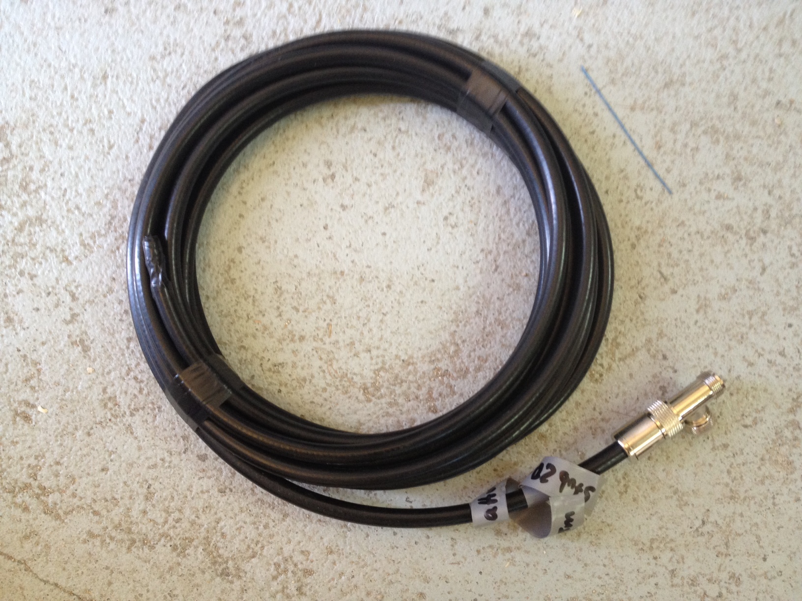
Make sure that the coax shield is cut back an inch (2 cms) at the open end of the coax stub. Voltages can get quite high and the last thing you want to have is an arcing coax cable 😉
Once finished with the stub, cover the open end with adhesive tape.
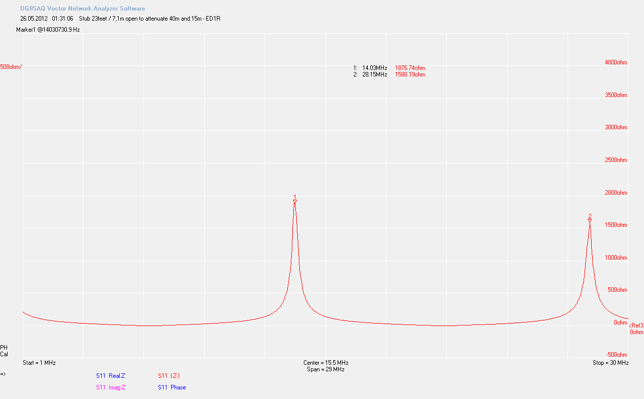
The picture above shows the absolute impedance on the 20m stub.
Coax stub filter #2 (40m - supressing 20m and 10m)
Length: 23 feet / 7,1 meter of RG213
Termination: Shorted
The termination has a huge influence on the performance! So don’t mess up the shorted and open stubs. On 40m, this stub has a quarter wavelength, and since it’s shorted it has a very high impedance. Again, use your preferred antenna analyzer and cut the cable for the highest |Z| at the center frequency (7,1 MHz in my case).
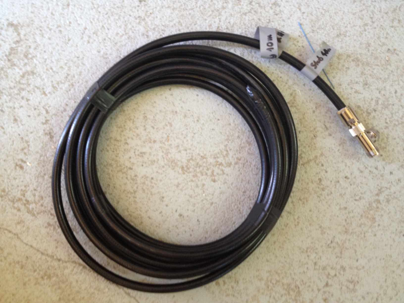
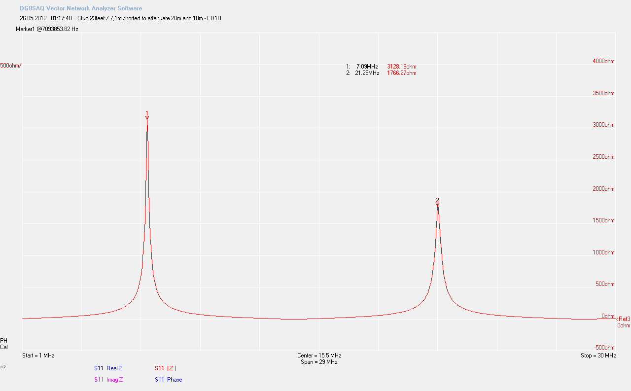
The picture above shows the 40m coax stub
The picture above shows the absolute impedance on the 20m stub (click to enlarge).
Installation
Connect the Coax Stub filters with a T-Connector directly between the output of your amplifier and your antenna cable. If you have already a bandpass filter in place, connect the stub with a T-connector between the output of the BPF and the antenna cable. That’s how we did it at ED1R.
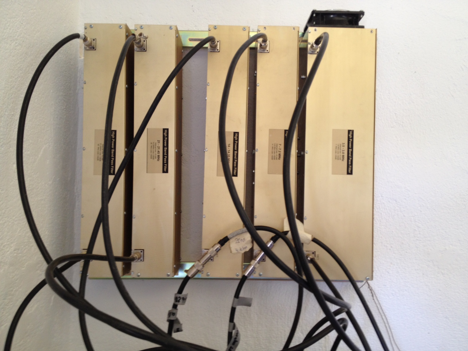
The picture above shows the ED1R High Power Bandpass Filters
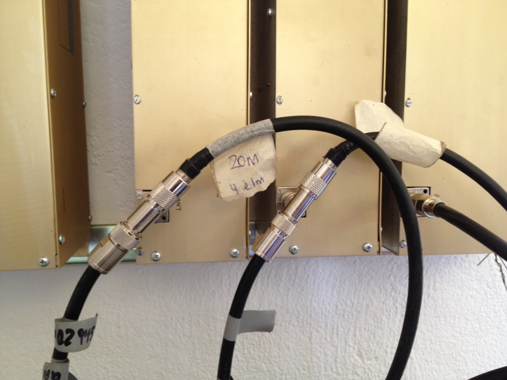
The stubs are connected with T-connectors between the output and the antenna cable
Conclusions
In the future, I will measure the exact filter curves with the added coax stubs [Update 10/5/2013: click here for the measurements. But at least my first impression is, that the stubs improve the attenuation. Coax stubs are a great, low-cost option to reduce the interferences between bands.
