
How to measure Ground Conductivity
Over the last few years, I spent a lot of time simulating antennas. One annoyance I encountered over and over was the unavailability of values for ground conductivity and the relative permittivity. Two figures have quite an impact on the antenna performance, especially on vertical antennas. This finally led to the conclusion that both figures need to be measured. In early 2012 I built a measurement kit and finally determined ground conductivity and relative permittivity at our contest station.
Motivation
Antenna literature only provides a few generic curves for the estimation of conductivity and the relative permittivity of soil (see below). Being unsure about the soil’s quality can mean a difference up to the factor 1000 (city vs rice paddy). While in practice you’ll have a rough idea if you are in the desert or rather close to the sea, everything in between is far from being clear. The better the data you feed into the simulation, the closer your results match in reality.

Some theory
Two conductors (metal rods) with known length and diameter are pushed in parallel into the soil. At the top, the impedance is measured. The setup is considered as a two-wire line with an open end. The impedance between the open ends (located in the soil) is transformed as a function of its geometrical properties and the mediums (here: soil) properties along the wire. Since the geometrical properties are known, the medium’s properties can be calculated with a bit of math. Fortunately, I could base my measurements on the intensive work of Hardy, DL1GLH who published a detailed summary of his research paper Measurement of the ground conductivity and relative permittivity with high frequency using an open wire line (OWL) on his website. If you are interested in the math behind this, please check out his website.
Online Calculator
While I had to calculate the results in Matlab, Hardy recently published an online ground conductivity calculator which does all the hard work for you. Therefore a Matlab license isn’t required anymore.
Setup
I measured the impedance with my DG8SAQ VNWA3 Vector Network Analyzer, my good old MacBookPro, and a homebrew two-wire line (see pictures below). Once the impedances were measured and written down, I calculated the conductivity (sigma) and relative permittivity (epsilon) with Mathworks Matlab.
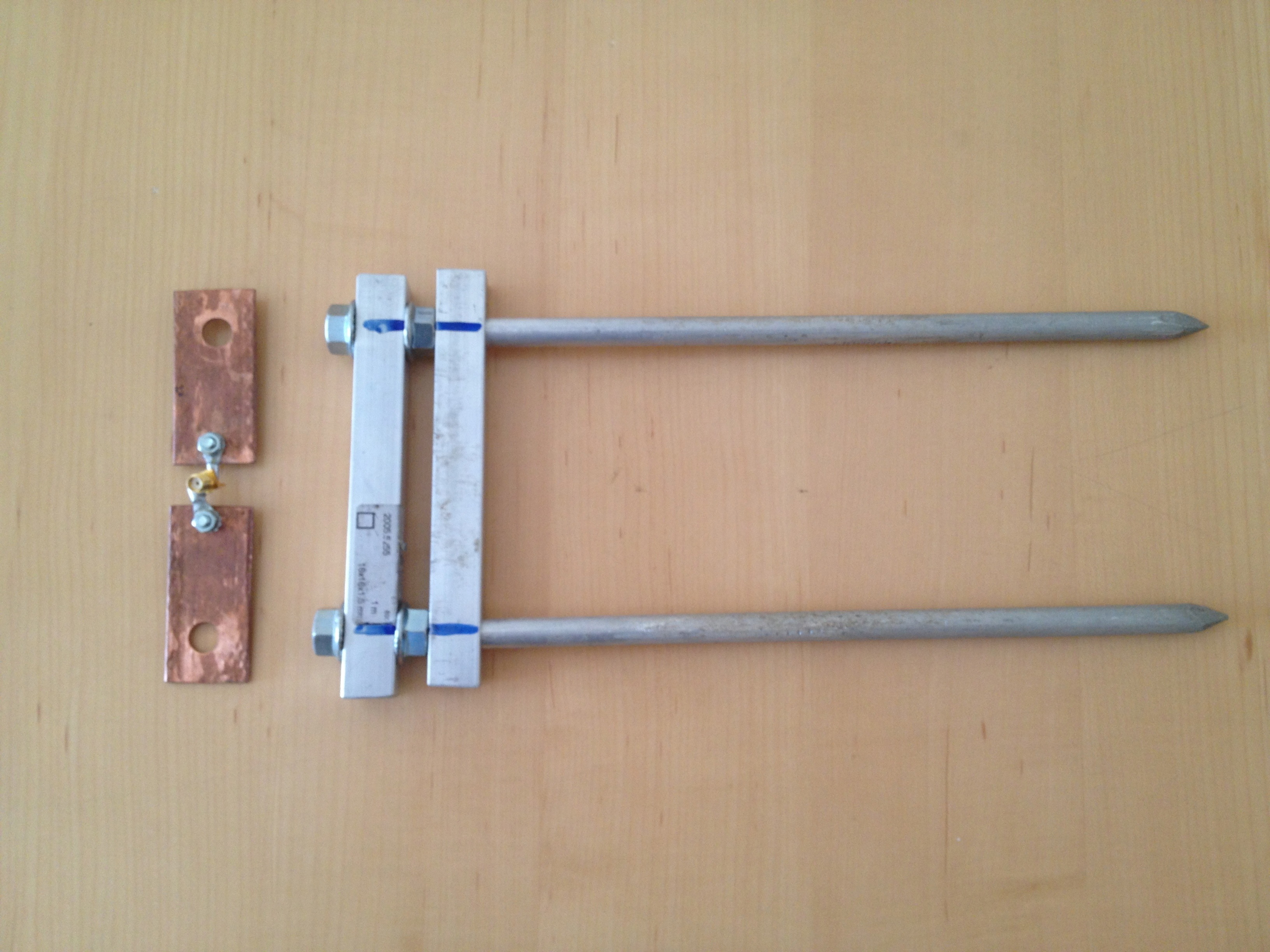
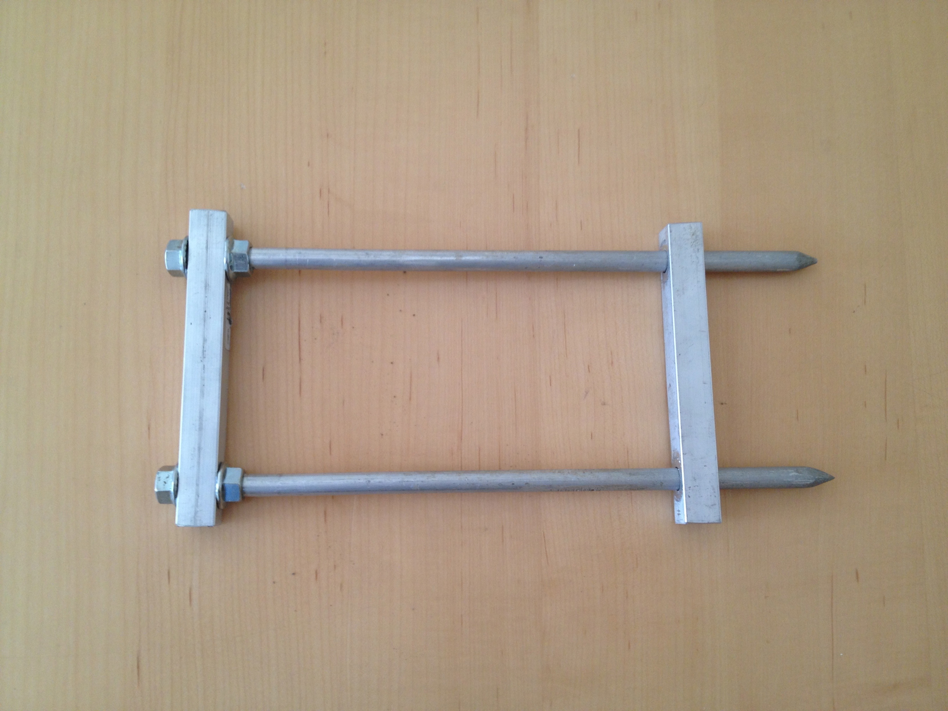
Two square bars are functioning as a guide to ensure that the metal rods are pushed at an equal distance into the earth.
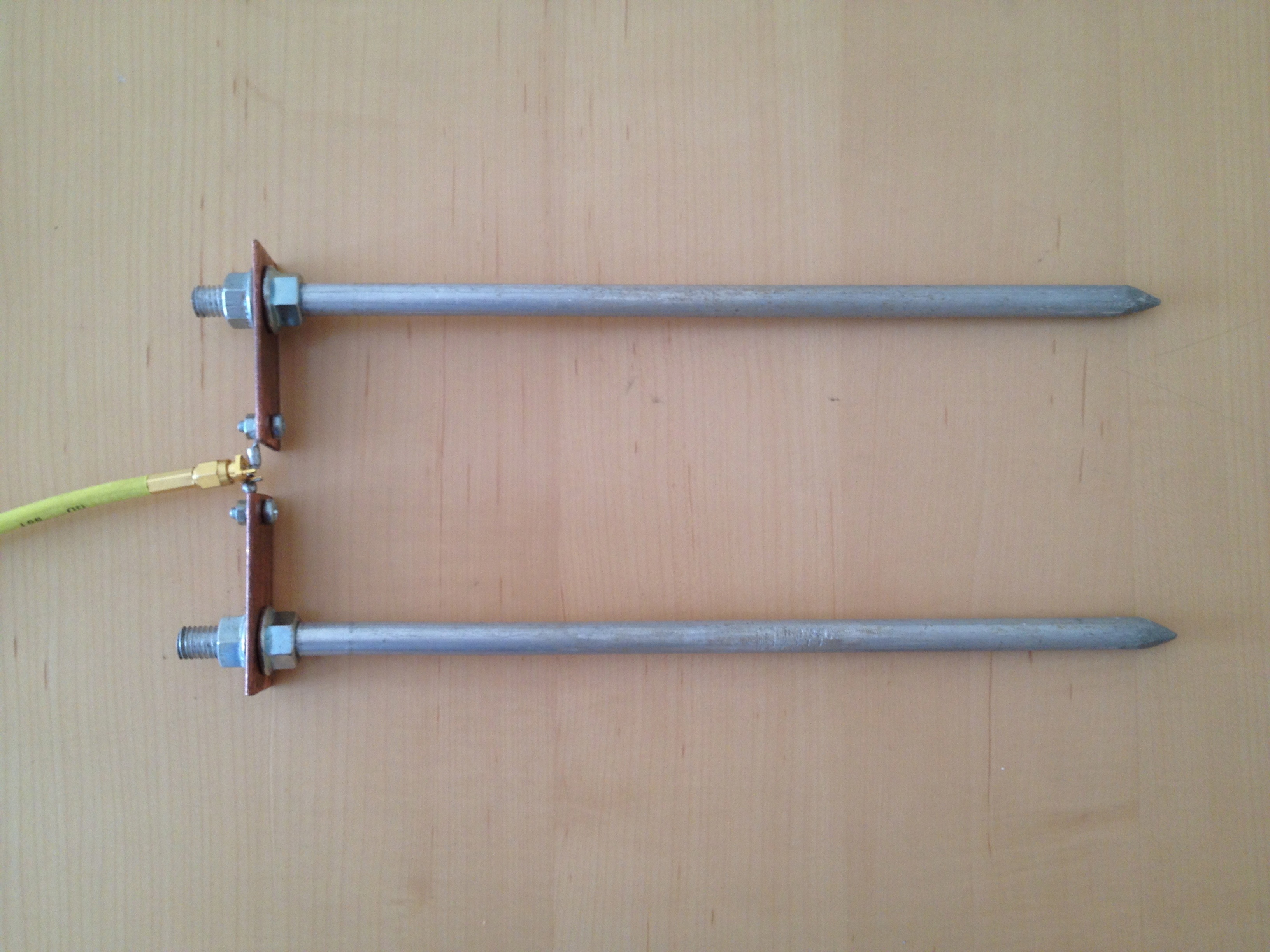
Once the metal rods are pushed into the earth, the square bar guides are removed. This is done by removing the nuts. The upper square bar is then replaced by the connecting bridge. The nuts are tightened and the VNWA is connected with a coax cable to the bridge.
Best practice
There are no perfect lengths, distance, and diameter for the two-wire line, but when you create your measurement kit you might find the following advice helpful. They are the outcome of my experiments:
- Avoid rods longer than 300mm. It’s quite difficult to penetrate agricultural soil for more than 300mm without using much force.
- Just use your foot or hand to push the rods into the soil. Don’t use a hammer or stone to push the wire-line into the ground. They must remain exactly parallel!
- If the soil is too hard, try to push the rods in a 45deg angle into the soil
- 5 - 10mm diameter of the rods is a good trade-off.
- Aluminium might be too soft. Try to use steel
- A distance of 50 - 100mm between the parallel rods should work well
- Impedance should be located between 30 Ohm - 500 Ohm
Performing the Measurements
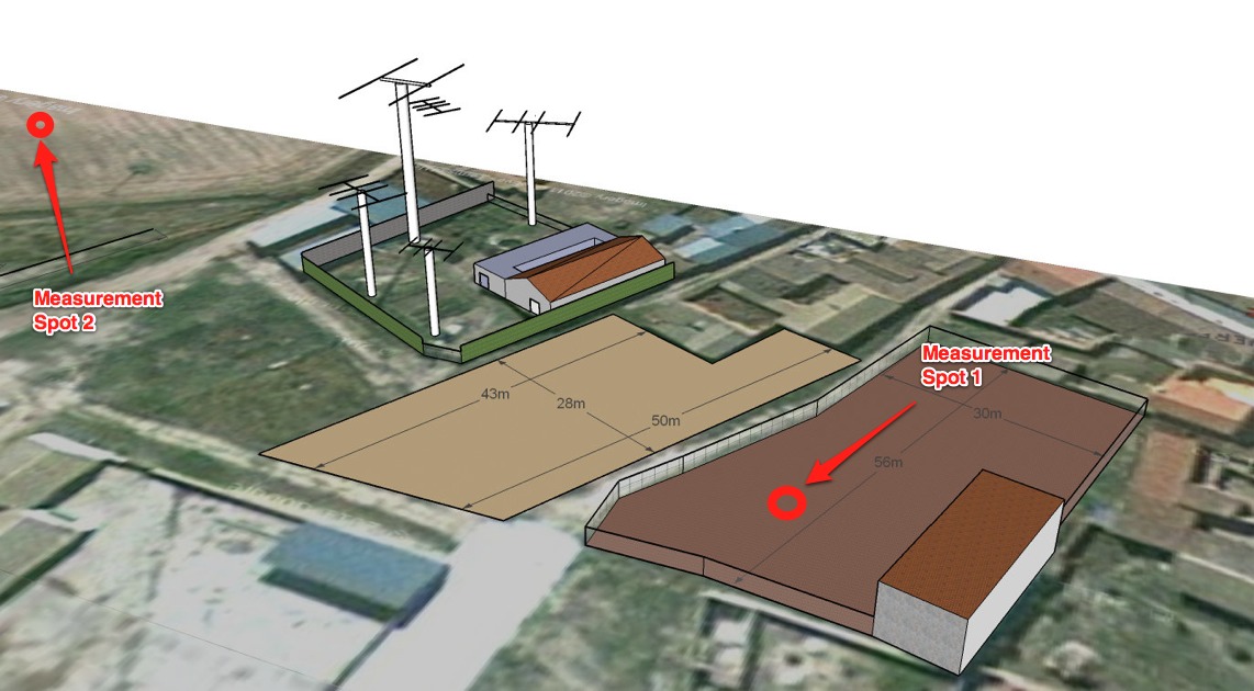
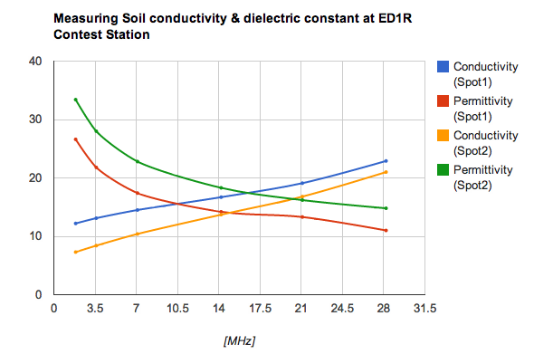
I performed the measurements at two different spots. Both spots are agriculturally used fields. Spot1 is a household garden and spot2 is a grain field. Find below some pictures taken during the measurements.
Results
Find below the results of the measurements taken at the two spots
Results Garden (Spot1)
<th align="center">
  Impedance [Ohm]
</th>

<th align="center">
  Conductivity [mS]
</th>

<th align="center">
  Permittivity
</th>
<td>
  236.3-j51.4
</td>

<td>
  12.2
</td>

<td>
  26.6
</td>
<td>
  208-j66.1
</td>

<td>
  13.1
</td>

<td>
  21.8
</td>
<td>
  170.5-j74.6
</td>

<td>
  14.5
</td>

<td>
  17.4
</td>
<td>
  125.7-j72.3
</td>

<td>
  16.7
</td>

<td>
  14.2
</td>
<td>
  96.5-j60.6
</td>

<td>
  19.1
</td>

<td>
  13.3
</td>
<td>
  85.7-j40.3
</td>

<td>
  22.9
</td>

<td>
  11
</td>
Results Grainfield (Spot2)
<th align="center">
  Impedance [Ohm]
</th>

<th align="center">
  Conductivity [mS]
</th>

<th align="center">
  Permittivity
</th>
<td>
  338.8-j157.0
</td>

<td>
  7.3
</td>

<td>
  33.4
</td>
<td>
  249.3-j161.8
</td>

<td>
  8.4
</td>

<td>
  28
</td>
<td>
  167.3-j138.6
</td>

<td>
  10.4
</td>

<td>
  22.8
</td>
<td>
  105.5-j99.2
</td>

<td>
  13.7
</td>

<td>
  18.3
</td>
<td>
  79.5-j72.3
</td>

<td>
  16.8
</td>

<td>
  16.2
</td>
<td>
  66.0-j48.6
</td>

<td>
  21
</td>

<td>
  14.8
</td>
Discussion
- When comparing the results with the charts taken out of the standard broadcast-engineering literature, they seem to be plausible. Considering that fertilizers are applied to both fields it is reasonable to find the values close to Rich agricultural land.
- I suppose that more fertilizers are applied to the garden, which could explain the better conductivity.
- The measured conductivity & relative permittivity explain the good results we achieve on the low bands during contests. We always have the impression to be loud on the low bands.
- Conductivity & relative permittivity can vary (significantly) between parcels of land. The two measurements are an indication but don’t paint the full picture. Consider that the area most influential is the nearfield and then the far-field up to a distance of 10 Lambda.
- Soil penetration is also an important fact which needs to be considered, especially with bad ground. Depending on the conductivity and frequency, the current can penetrate up to 100 meters deep the underlying ground. Make sure you know the various layers of soil you are standing on.
Conclusion
The two-wire method is an easy way to determine the conductivity and relative permittivity of soil. With amateur means, fairly precise results can be achieved. Measurements should be taken at various points since the ground characteristics can change significantly between two parcels of land. The soil quality at ED1R is close to Rich agricultural land. Now further antenna simulations can be improved by using the exactly determined values.
Resources
- DL1GLH’s work on measuring soil conductivity
- DL1GLH’s online calculator
- ITU World Atlas of Ground Conductivities
- Professional Ground Penetration Radar Equipment
As always I would be delighted to hear your thoughts on this topic!
