
FA-SDR-TRX part #2 – The Receiver
After a systems view on the FA-SDR-TRX, it’s time to go into more detail. This post is dedicated to FA-SDR-TRX’s receiver.
Other posts in this series:
FA-SDR-TRX - part #1 - a Systems View
FA-SDR-TRX - part #2 - the Receiver
FA-SDR-TRX - part #3 - the Transmitter
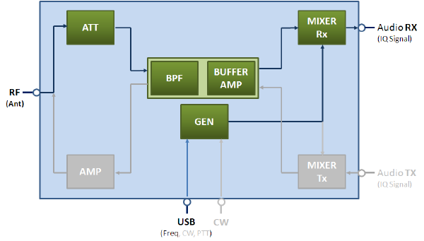
Block diagram
Let’s recap shortly the block diagram. I think it’s useful to have it again present. However, I don’t want to explain it anymore. It was already explained in a previous post.
What I would like to do is to pick out the components of the receiver and get more precise about them.
What I would like to do is to pick out the components of the receiver and get more precise about them.
Attenuator

FA-SDR-TRX has incorporated a switchable attenuator as a first element in the RF chain. The attenuation is selectable in three steps: 0dB, 6dB, and 12dB with a rotary switch on the front panel.
Bandpassfilter / Preselector

To keep the design as simple as possible a manual preselector was implemented. The design is similar to Thomas, DL7AV’s approach. The impedance is transformed from 50Ohm to 5,6 Ohm with a trifilar transformer. On this low impedance, the selectivity is gained by a series resonance filter consisting of 4 switchable inductors (800nH-22µH) and a tunable capacitor (20pF-225pF). Afterward, the impedance is transformed again back from 5,6Ohm to 50Ohm with another transformer (Mini-circuits T-622). The following diagram shows the selectivity and harmonic suppression on 40m / 7MHz.

- Harmonic on (7 MHz) +10,7dB (normalized: 0dB)
- Harmonic on (14 MHz) -21,8dB (normalized: -32,5dB)
- Harmonic (21MHz) -27,8dB (normalized: -38,5dB)
On the picture of the FA-TRX-Prototype, the preselector control knobs can be seen. The following five positions are available:
- 866kHz … 35MHz (Bypass)
- 1,7MHz … 4,3MHz
- 2,9MHz … 7,5MHz
- 5,1MHz … 14,2MHz
- 11,1MHz … 33MHz
Once the right position is selected, the variable capacitor is tuned on the maximum signal level.
Please note that this bandpass filter/preselector is a “shared” component. It is also used during transmission.
Buffer Amplifier

To ensure the preselector’s good performance, a proper impedance (50Ohm) at its input and output gates is crucial. This is done with the MMIC (Monolithic Microwave Integrated Circuit) SGA5289. The fixed gain of this amplifier is 13dB (0Hz…5GHz). Besides a very high IP3 (>33dBm) the return loss on the input and output gate is better than -25dB. This ensures that unwanted signals from the following stage, the sampling detector, aren’t transmitted unintentionally during the reception. Besides all the mentioned advantages, it has to be mentioned, that the amplifier also reduces the overall IP3 of the receiver. Somehow it’s a kind of practical compromise. This amplifier is also a shared component.
RX Mixer

FA-SDR-TRX uses the well-known Tayloe (sampling) detector. The author, Harald, DL2EWN conducted a series of tests with some unknown and other better known switching ICs. He tested the ICs within the receiver circuit and compared the receiver’s sensitivity (MDS), intermodulation (IP3), and image rejection. The following ICs have been tested:
- MAX4544
- FST3253
- 74HC4066
- MAX4614
- 74LVC4066
While some of them showed only usable results below 10MHz, others performed well up to 30MHz. Finally, 74LVC4066 showed the best overall performance. The advantages of this IC are a low switching time and a low On-resistance. Another important point was, that test results were reproducible with several samples.
Other tests showed, that this IC can even be used to sample 60MHz (3rd harmonic / 16,6MHz) or 145MHz signals (5th harmonic / 29MHz). The screenshot below shows the receiver on 50MHz. The losses of the mixer (3. harmonic) are around about 10dB. At the same time, these losses are compensated with the SGA5289 Buffer amp. In conjunction with a 6m bandpass filter, a proper 50MHz receiver could easily be realized.
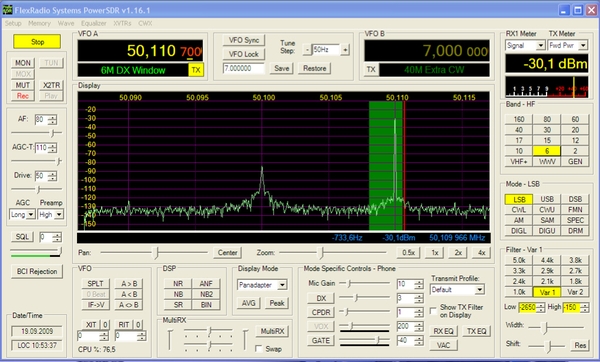
Please note that the image frequency rejection is >90dB (50.110MHz vs. 50.090MHz) with optimized Software and Hardware.
The clock for the 74LVC4066 sampling IC is provided by the Signal Generator via a 74ACT74 Flipflop IC. After the “mixing” / down conversion, the four audio signals (0° / 180° / 90° / 270°) are combined in low noise Rail-to-Rail op-amps. The selected OPA2350 was configured externally to get a compromise between low noise and a high dynamic range.
Generator

The signal which drives the mixer is generated with Silabs Si570 programmable VCXO. The Si570 has an I2C interface. G0BBL, G8BTR, M0PUB, PE1NNZ, and DG8SAQ did a tremendous job in developing a general-purpose, low-cost RF Synthesizer based on the Si570. The publisher Funkamateur offers this synthesizer as a USB ready-to-go device under the name FA-SY1. This device is used without modification in the FA-SDR-TRX. To avoid ground loops from the PC via the USB, all signals are insulated galvanically with a transformer and optocouplers.
